

Before we start... some ramblings
- oscholz5
- 26. Dez. 2021
- 4 Min. Lesezeit
Aktualisiert: 28. Dez. 2021
Before we get deep into building your own, homemade video console, allow me to write a little about what it is going to do.
The main purpose of this project is to have fun and maybe teach you some electronics on the way. That also means I'm not responsible if you don't get it to work, it doesn't do what you think it does, it's not 100% compatible to all games out there, I won't help you debugging it or heaven forbid solder one for you. The purpose of these pages is that you can do that yourself and I don't have to. Hence DIY.
Also, if you need to shield the board's electromagnetic radiation, need to conform to some standard or building electronics is restricted in your country, you need to perform EMC conformity tests, all that stuff is your responsibility. (Hint: building non-commercial experimental electronics are exempt from mandatory EMC tests in the EU, but of course you're still responsible for possible interferences caused by your experiments). Personally I recommend moving to a country with as few restrictions as possible, such as Bora Bora or Belize.
What features does this project have?
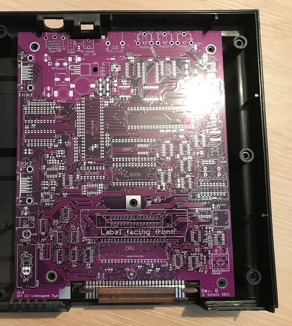
That's actually a very good question! This project only covers a blank circuit board. You can use it to build a ColecoVision compatible "clone", but it can also be expanded by adding optional circuitry the original Coleco didn't have. So it can either be a standalone experimental board, but it also happens to fit both PAL and NTSC enclosures, so if you have a dead motherboard, you can use this board as a replacement. If you don't own an original CV and you want an enclosure, maybe you're in luck, because I plan to upload a 3D printable enclosure for your homemade console.
Also, the bulky CV power supply is no longer available and prone to failure, so this project uses a standard "wall wart" power supply you probably still have in your attic.
Together with the onboard RGB circuitry these alone are reasons enough to upgrade your existing ColecoVision mainboard!
Where to get the parts
All standard components still in production today (2021), except for sound and video chips, which are readily available on eBay. The major ICs use easy to handle DIL packages and can (and should) be socketed. The surface mount stuff is mostly "Small Outline" (SO) and SOT23 which are easy to solder by hand. Only two ICs in the RGB section are smaller, but can also be soldered manually with a steady hand and a little patience.
A good source for most of the components is Mouser. The power switch should be recycled from a ColecoVision mainboard, if that's not an option, a good alternative is available from RS components.
One important thing to note: no special equipment is necessary, the design does not involve GALs, CPLDs or even an FPGA (although that would have greatly simplified the circuit). The point was that everybody should be able to build this, and if you're doing an FPGA "CV on a chip" you may just as well go Raspberry Pi. So all you need for this project is a good, old-fashioned EPROM burner. And yes, EPROMs are still being made and readily available!
Feature list
Without any further ado, here's a list of features resp. advantages this project board has over the original CV even if you don't add anything beyond a CV clone:
Fits both NTSC and PAL enclosures
RGB output using a standard Sega Genesis 2 cable with Mini-DIN plug. (For the experts: TMS-RGB is on board)
Suitable for both 2.1mm and 2.5mm standard DC plug power supplies
Wide power supply range: 8-16V, min. 1A recommended (depends on what you hook up to expansion bus)
Onboard generation of all required voltages from single power supply
You can recycle original ColecoVision power and reset switches or use modern alternatives
Controller port ICs are socketed and feature optional protection diodes
Supports 8, 32 or 64K BIOS EPROMs
Supports different crystal oscillators using selectable divider
Functional expansion port supporting most signals
And now for the extra stuff the original CV never had:
32K ADAM RAM standard, starts up in CV compatible 1K memory mode
ADAM-RAM compatible with the (never released) 1983 "Super Game" expansion module #3
Up to 64K of Adam RAM using ADAM compatible memory register
Optional 64K BIOS EPROM can be used with modified BIOS to support built-in game of up to 32K using ADAM compatible memory register
Optionally supports popular AY-3-8910 sound chip used in MSX and Atari ST home computers and many arcade boards
Stereo output with AY-3-8910 sound chip, with optional stereo/mono switch
Optional USB port can be used to download games via USB using custom BIOS, which is useful for fast turnaround when testing games on real hardware
Optional pause key
Optional Power-on LED
Optional Chinch A/V jacks for use with Expansion module #1 or if RGB isn't built
Optional space for GAL memory devices for your own experiments
Optional stereo power amp for building arcade cabinet
Optional speech add-on board (requires AY3-8910 sound chip) using SP0256-AL2 speech processor
So, as you can see, this is quite a list! I hope this whets your appetite and you want to find out more!
A couple more (important) things to note:
All resistors and most capacitors are SMD 0805 unless otherwise noted! Check the circuit board footprint before ordering parts, it's easy to order a part of the wrong size!
Please use sockets for all DIL parts, but on't put them in place unless the IC is going to be installed.
I really recommend to populate the parts in the order I give here. It makes testing and possibly debugging so much easier!
Double check the orientation of all ICs! Some TTLs are upside down! Without the right equipment the surface mount ICs can be a pain to remove!
Some (very few!) parts are on the solder side. When looking for a part location, look there as well!
If you want to install the board in an original ColecoVision case, you may need to cover the board edges with Kapton tape to prevent the metal shield from shorting anything! Normally the shield shouldn't reach any part of the PCB that's NOT ground, but double check to be sure!
A lot of stuff is optional or experimental, plan well which parts you want to use!
And a final note: You do everything at your own risk!


Kommentare